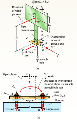
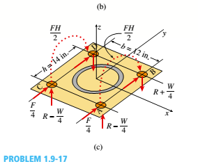
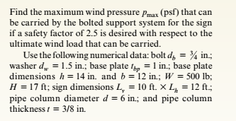
A sign of weight W is supported at its base by four bolls anchored in a concrete footing. Wind pressure P acts normal to the surface of the sign; the resultant of the uniform wind pressure is force fat the center of pressure (C.P). The wind force is assumed to create equal shear forces F/4 in the y direction at each boll (see figure parts a and c). The overturning effect of the wind force also causes an uplift force R at bolts A and C and a downward force (— R) al bolts B and D (see figure part b). The resulting effects of the wind and the associated ultimate stresses for each stress condition are normal stress in each boll ( h — 60 ksi); shear through the base plate (t h = 17 ksi); horizontal shear and bearing on each bolt ( t f u r = 25 ksi and cr^ = 75 ksi): and bearing on the bottom washer at B (or D) (a b o r = 50 ksi).
A sign of weight W is supported at its base by four bolls anchored in a concrete footing. Wind pressure P acts normal to the surface of the sign; the resultant of the uniform wind pressure is force fat the center of pressure (C.P). The wind force is assumed to create equal shear forces F/4 in the y direction at each boll (see figure parts a and c). The overturning effect of the wind force also causes an uplift force R at bolts A and C and a downward force (— R) al bolts B and D (see figure part b). The resulting effects of the wind and the associated ultimate stresses for each stress condition are normal stress in each boll ( h — 60 ksi); shear through the base plate (t h = 17 ksi); horizontal shear and bearing on each bolt ( t f u r = 25 ksi and cr^ = 75 ksi): and bearing on the bottom washer at B (or D) (a b o r = 50 ksi).
A sign of weight W is supported at its base by four bolls anchored in a concrete footing. Wind pressure P acts normal to the surface of the sign; the resultant of the uniform wind pressure is force fat the center of pressure (C.P). The wind force is assumed to create equal shear forces F/4 in the y direction at each boll (see figure parts a and c). The overturning effect of the wind force also causes an uplift force R at bolts A and C
and a downward force (— R) al bolts B and D (see figure part b). The resulting effects of the wind and the associated ultimate stresses for each stress condition are normal stress in each boll (
h — 60 ksi); shear through the base plate (t
h = 17 ksi); horizontal shear and bearing on each bolt ( t
fur = 25 ksi and cr^ = 75 ksi): and bearing on the bottom washer at B (or D) (a
bor = 50 ksi).
As shown, an L-shaped bar is supported by a pin at joint A. The bar's dimensions are aaa = 620 mmmm and bbb = 400 mmmm , and the bar is subjected to a force with magnitude FFF = 5.05 kNkN at joint B. Ignoring the bar's weight, find the actual orientation of the applied force. What is the value of the angle θθtheta?
Suppose beam of the list on a comer A and against a wall at the point B( No friction any
surfaces) The Beam angle 30 degrees. The force between the beam and the Conner (at point
A) is 10N, Calculate X Component of force this force given the coordinate axes defined in
the Figure.
Suppose a beam of lengh L sts ona comer Aend againat a wal at point 8 (Aume na tion on any sufacen). The bean mtnde
degrees with the comer e shown in the gun Asune he force betenen the bean and the comer a pont Ajis 10N, cae
ha bron given the coordeatn auna dafred in the fgum
II.
Calculate all the Support reaction at B. For the purposes of Submission Divide all
your force Values by q0*a (ie. Fa/(q0*a), thereby yielding a unitless number
90
D
E
2a
B.
The Straw Hat crew on their journey to Laugh Tale Island found a big treasure box (W). Luffy
wanted to place the treasure box (W) as shown in the figure. A 100-mm x 300 mm rectangular
beam is supported in a horizontal position. At point "A", it is being held by a pin and at "B" by a
cable BD inclined 3 vertical to 4 horizontal. Assume all forces are applied to the beam along its
central axis. Given that Fcparallel to grain = 10.50 MPa, W = 79 kN and E = 13800 MPa. Neglecting
the weight of the beam and cable, determine whether the design is safe.
Cable
2.4 m
2.4 m
Need a deep-dive on the concept behind this application? Look no further. Learn more about this topic, mechanical-engineering and related others by exploring similar questions and additional content below.
EVERYTHING on Axial Loading Normal Stress in 10 MINUTES - Mechanics of Materials; Author: Less Boring Lectures;https://www.youtube.com/watch?v=jQ-fNqZWrNg;License: Standard YouTube License, CC-BY


 Mechanics of Materials (MindTap Course List)Mechanical EngineeringISBN:9781337093347Author:Barry J. Goodno, James M. GerePublisher:Cengage Learning