
Mechanics of Materials (MindTap Course List)
9th Edition
ISBN: 9781337093347
Author: Barry J. Goodno, James M. Gere
Publisher: Cengage Learning
expand_more
expand_more
format_list_bulleted
Concept explainers
Videos
Textbook Question
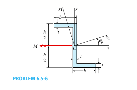
Chapter 6, Problem 6.5.6P
The Z-section of Example D-7 is subjected to M = 5 kN · m, as shown.
Determine the orientation of the neutral axis and calculate the maximum tensile stress c1and maximum compressive stress ocin the beam. Use the following numerical data: height; = 200 mm, width ft = 90 mm, constant thickness a = 15 mm, and B = 19.2e. Use = 32.6 × 106 mm4 and I2= 2.4 × 10e mm4 from Example D-7
Expert Solution & Answer

Trending nowThis is a popular solution!

Students have asked these similar questions
Below Figure shows the section of an angle purlin. A bending moment of
5 kN.m is applied to the purlin in a plane at an angle of 30 deg to the
vertical y axis. If the sense of the bending moment is such that both its
components Mx and My produce tension in the positive xy quadrant,
calculate the maximum direct stress in the purlin, stating clearly the point
at which it acts. *
100 mm
E
10mm
30
C D
-10mm
57 MPa.
89 MPa.
Non Above
O 72 MPa.
125mm
the same magnitude of stress in compression.
For points not on a surface of the beam, we can use
Omax /c = -o/y
Part A - Moment Required to Produce a Given Stress
to rewrite the flexure formula in the more general
form
The cross-section of a wooden, built-up beam is shown below. The dimensions are L = 220 mm
and w = 40 mm.
Му
(Figure 1)
Determine the magnitude of the moment M that must be applied to the beam to create a
compressive stress of op = 30 MPa at point D. Also calculate the maximum stress developed
in the beam. The moment M is applied in the vertical plane about the geometric center of the
beam.
Figure
Express your answers, separated by a comma, to three significant figures.
'D
M =,
kN-m,
MPa
Omax =
the same magnitude of stress in compression.
For points not on a surface of the beam, we can use
Omax /c = -o/y
Part A - Moment Required to Produce a Given Stress
to rewrite the flexure formula in the more general
form
The cross-section of a wooden, built-up beam is shown below. The dimensions are L = 220 mm
and w = 40 mm.
Му
(Figure 1)
Determine the magnitude of the moment M that must be applied to the beam to create a
compressive stress of op = 30 MPa at point D. Also calculate the maximum stress developed
in the beam. The moment M is applied in the vertical plane about the geometric center of the
beam.
Figure
Express your answers, separated by a comma, to three significant figures.
> View Available Hint(s)
'D
Vo AEd
vec
?
kN-m,
MPа
M =.
Omax=
Submit
Chapter 6 Solutions
Mechanics of Materials (MindTap Course List)
Ch. 6 - A composite beam is constructed using a steel...Ch. 6 - A wood beam is strengthened using two steel plates...Ch. 6 - A composite beam consisting of fiberglass faces...Ch. 6 - A wood beam with cross-sectional dimensions 200 mm...Ch. 6 - A hollow box beam is constructed with webs of...Ch. 6 - A r o lukI f/frm f «m t ub e of ou t sid e d ia...Ch. 6 - A beam with a guided support and 10-ft span...Ch. 6 - A plastic-lined steel pipe has the cross-sectional...Ch. 6 - The cross section of a sand wie h beam consisting...Ch. 6 - The cross section of a sandwich beam consisting of...
Ch. 6 - A bimetallic beam used in a temperature-control...Ch. 6 - A simply supported composite beam 3 m long carries...Ch. 6 - A simply supported wooden I-beam with a 12-ft span...Ch. 6 - -14 A simply supported composite beam with a 3.6 m...Ch. 6 - -15 A composite beam is constructed froma wood...Ch. 6 - A wood beam in a historic theater is reinforced...Ch. 6 - Repeat Problem 6.2-1 but now assume that the steel...Ch. 6 - Repeat Problem 6.2-17 but now use a...Ch. 6 - A sandwich beam having steel faces enclosing a...Ch. 6 - A wood beam 8 in. wide and 12 in. deep (nominal...Ch. 6 - A simple beam of span length 3.2 m carries a...Ch. 6 - A simple beam that is 18 ft long supports a...Ch. 6 - The composite beam shown in the figure is simply...Ch. 6 - The cross section of a beam made of thin strips of...Ch. 6 - Consider the preceding problem if the beam has...Ch. 6 - A simple beam thai is IS ft long supports a...Ch. 6 - The cross section of a composite beam made of...Ch. 6 - A beam is constructed of two angle sections, each...Ch. 6 - The cross section of a bimetallic strip is shown...Ch. 6 - A W 12 x 50 steel wide-flange beam and a segment...Ch. 6 - A reinforced concrete beam (see figure) is acted...Ch. 6 - A reinforced concrete T-beam (see figure) is acted...Ch. 6 - A reinforced concrete slab (see figure) is...Ch. 6 - A wood beam reinforced using two channels is...Ch. 6 - A wood beam reinforced by an aluminum channel...Ch. 6 - A beam with a rectangular cross section supports...Ch. 6 - A wood beam with a rectangular cross section (see...Ch. 6 - Solve the preceding problem for the following...Ch. 6 - A simply supported wide-flange beam of span length...Ch. 6 - Solve the preceding problem using the fol...Ch. 6 - A wood cantilever beam with a rectangular cross...Ch. 6 - Solve the preceding problem for a cantilever beam...Ch. 6 - A 2-m-long cantilever beam is constructed using a...Ch. 6 - A wood beam AB with a rectangular cross section (4...Ch. 6 - A steel beam of I-section (see figure) is simply...Ch. 6 - A cantilever beam with a wide-flange cross section...Ch. 6 - Solve the preceding problem using a W 310 x 129...Ch. 6 - A cantilever beam of W 12 × 14 section and length...Ch. 6 - A cantilever beam built up from two channel...Ch. 6 - A built-Lip I-section steel beam with channels...Ch. 6 - Repeat Problem 6.4-14 but use the configuration of...Ch. 6 - A beam with a channel section is subjected to a...Ch. 6 - A beam with a channel section is subjected to a...Ch. 6 - An angle section with equal legs is subjected to a...Ch. 6 - An angle section with equal legs is subjected to a...Ch. 6 - A beam made up all woun equal leg angles is...Ch. 6 - The Z-section of Example D-7 is subjected to M = 5...Ch. 6 - The cross section of a steel beam is constructed...Ch. 6 - The cross section of a steel beam is shown in the...Ch. 6 - A beam with a semicircular cross section of radius...Ch. 6 - .10 A built-up bourn supporting a condominium...Ch. 6 - Asteelpost (E = 30 × 106 psi) having thickness t =...Ch. 6 - A C 200 x 17.1 channel section has an angle with...Ch. 6 - A cold-formed steel section is made by folding a...Ch. 6 - A simple beam with a W 10 x 30 wide-flange cross...Ch. 6 - Solve the preceding problem for a W 250 × 44.8...Ch. 6 - A beam of wide-flange shape, W 8 x 28, has the...Ch. 6 - Solve the preceding problem for a W 200 × 41,7...Ch. 6 - Calculate the distance e from the cent crime of...Ch. 6 - Calculate the distance e from the centerline of...Ch. 6 - The cross section of an unbalanced wide-flange...Ch. 6 - The cross section of an unbalanced wide-flange...Ch. 6 - The cross section of a channel beam with double...Ch. 6 - The cross section of a slit circular tube of...Ch. 6 - The cross section of a slit square tube of...Ch. 6 - The cross section of a slit rectangular tube of...Ch. 6 - A U-shaped cross section of constant thickness is...Ch. 6 - Derive the following formula for the distance e...Ch. 6 - Derive the following formula for the distance e...Ch. 6 - The cross section of a sign post of constant...Ch. 6 - A cross section in the shape of a circular arc of...Ch. 6 - Determine the shape factor f for a cross section...Ch. 6 - (a) Determine the shape factor/for a hollow...Ch. 6 - A propped cantilever beam of length L = 54 in....Ch. 6 - A steel beam of rectangular cross section is 40 mm...Ch. 6 - .5 Calculate the shape factor j for the...Ch. 6 - Solve the preceding problem for a wide-flange beam...Ch. 6 - Determine the plastic modulus Z and shape...Ch. 6 - Prob. 6.10.8PCh. 6 - Prob. 6.10.9PCh. 6 - Prob. 6.10.10PCh. 6 - A hollow box beam with height h = 16 in,, width h...Ch. 6 - Solve the preceding problem for a box beam with...Ch. 6 - A hollow box beam with height h = 9.5 in., inside...Ch. 6 - Solve the preceding problem for a box beam with...Ch. 6 - The hollow box beam shown in the figure is...Ch. 6 - Prob. 6.10.16PCh. 6 - Prob. 6.10.17PCh. 6 - A singly symmetric beam with a T-section (see...Ch. 6 - A wide-flange beam with an unbalanced cross...Ch. 6 - .20 Determine the plastic moment Mpfor beam having...
Knowledge Booster


Learn more about
Need a deep-dive on the concept behind this application? Look no further. Learn more about this topic, mechanical-engineering and related others by exploring similar questions and additional content below.Similar questions
- The cross section of a sign post of constant thickness is shown in the figure. Derive the formula for the distance e from the cent crime of the wall of the post to the shear center S: where I2. = moment of inertia about the z axis. Also, compare this formula with that given in Problem 6.9-11 for the special case of ß = 0 here and a = h/2 in both formulas.arrow_forwardThe bending moment M is applied to the box beam in the x-y plane at the orientation show below. (a) Determine the maximum magnitude of the bending moment M so that the tensile bending stress in the member does not exceed 15 ksi. (b) Determine the angle that the neutral axis makes with the y-axis. (c) The position or positions on the beam where the maximum compressive bending stress occurs given your answer in a. Clearly indicate this on the figure below (also calculate the values) 4 in. B 4 in. M 6 in. 6 in.arrow_forwardFor the beam shown, there is a roller at 1.5 feet from the left and a pinned support at the far-right end. Two loads are applied: a 450-kip vertical load and a 15 kip*ft moment. The cross-sectional shape of the beam is shown on the right. What is the maximum stress on this beam? Note: A kip is a kilopound.arrow_forward
- For the beam shown at right, determine the following: P= 1800 lb a. Maximum tensile bending stress b. Transverse shear stress at a the junction of the "TEE" (i.e., 2" above the neutral axis). c. Transverse shear stress at the neutral axis - 7.5 ft- - 7.5 ft- (a) d. Draw the stress elements -10 in. representing the state of stress at the junction of the “TEE" and at the neutral axis. | 2 in. 4 in. -N- 1600 10 in. 8 in. 42 in.k- (b)arrow_forwardMA MB= Mc= MD= Required information For the beam shown, find the reactions at the supports and plot the shear-force and bending-moment diagrams. V=50 lbf/in and V2 = 7 in. NOTE: This is a multi-part question. Once an answer is submitted, you will be unable to return to this part. Hinge = 1400 lbf/ A BI AC R₂ R₁ 4 in 4 in 2 in V1 Determine the values of the moments at points A, B, C, and D. lbf.in lbf.in lbf.in Ibf.in V2 D R₂arrow_forwardConsider the following values in the given beam above: L1=6m L2 = 2 m L3 = 4 m L4=3m L5=2 m L6=1m W1 = 90 kN/m W2 = 30 kN/m P = 50 kN M = 60 kN-m Point E is an internal hinge W1 B L2 L3 2 m E W2 L5 L6 Harrow_forward
- For the beam shown, use only singularity functions. V₁ = 45 lbf/in and V/₂ = 5 in. NOTE: This is a multi-part question. Once an answer is submitted, you will be unable to return to this part. 0 1400 lbf Hinge JA B₁ C R₂ R₁ 4 in 4 in 2 in V1 V2 D R₂ + What is the value of the peak moment between points Cand D? The peak moment between points C and Dis Ibf.in.arrow_forwardThe built-up beam is subjected to a moment of M = 80 kNm. Variable d₁ d₂ d3 da Values for the figure are given in the following table. Note the figure may not be to scale. d5 d3 de d₁ Value 128 mm 22 mm 276 mm 11 mm 138 mm d4 12 mm M₁ de d5 a. Determine the distance from the Neutral Axis to the top of the beam, N.A. b. Determine the mass moment of inertia of the beam, I. Determine the max compressive stress acting on the beam, compression c. d. Determine the max tensile stress acting on the beam, tension.arrow_forwardM H. W Figure-2 A wide flange beam is subjected to a moment as shown in Figure-2. If M=10 kN.m, H=212 mm, W=170 mm, d=11 mm, t-18 mm and 0=64°; Determine the moment of inertia (mm) about the axis-z. Determine the moment of inertia (mm*) about the axis-y. Determine the normal stress (MPa) due to bending at point A. If it is compressive stress, use - sign. Determine the orientation angle, B (degree), of the neutral axis relative to the +z axis.arrow_forward
- Given the beam shown below, determine the shear force and bending moment at point C. Given the dimensions a = 2 m, b = 5.9 m and c = 2 m, and the load intensities e = 10 kN/m and f = 2 kN/m. e kN/m f kN/m am bm cm A B D Shear force (observe the up on the left, down on the right positive sign convention): SFc = Number Units (tolerance 0.2 kN) Bending moment (observe the sagging positive sign convention): BMc = Number Units (tolerance 1 kN*m)arrow_forwardSIMPLE STRESSES 15 KN/m 1. The beam shown in the figure carries distributed loads. Design the square (a x a) cross-section of the timber columns of the beam. Column A has the same dimensions 1.50 m 3 m 1 m 10 KN/m 1 m as Column B. The strength of the column is 80 MPa. Express the dimensions of the column in whole number. 10 KN/m Aarrow_forwardQuestion 4 A beam made up of two unequal leg angles is subjected bending moment M having to a its vector at an angle 0 to the z axis as shown in Figure Q4 For the position shown, determine the onentation of the neutral axis 4.1 Calculate the maximum tensile stress and maximum compressive stress in the beam 4.2 Assume that 0 3.5 kNm 30° and M = 120 mmx80 mmx12 mm 120 mm 12 mm 80 mm Figure Q4arrow_forward
arrow_back_ios
SEE MORE QUESTIONS
arrow_forward_ios
Recommended textbooks for you
 Mechanics of Materials (MindTap Course List)Mechanical EngineeringISBN:9781337093347Author:Barry J. Goodno, James M. GerePublisher:Cengage Learning
Mechanics of Materials (MindTap Course List)
Mechanical Engineering
ISBN:9781337093347
Author:Barry J. Goodno, James M. Gere
Publisher:Cengage Learning
Everything About COMBINED LOADING in 10 Minutes! Mechanics of Materials; Author: Less Boring Lectures;https://www.youtube.com/watch?v=N-PlI900hSg;License: Standard youtube license